IMG_20210401_212734

esp8266 VOICE CONTROLLED HOME AUTOMATION WITH AMAZON ALEXA

Warning

This project deals with high voltage

Description

The purpose of this project is to create an innovative device that can be controlled using Amazon Alexa voice commands, allowing users to control up to three appliances with ease. The device will have three relays, which can be linked to any three appliances, providing users with a convenient way to automate their home or office.

The device will be designed to be compatible with most appliances and will be easy to install, with no complicated wiring required. Once installed, users can connect the device to their Wi-Fi network and link it to their Alexa account, enabling them to control their appliances using voice commands.

In addition to voice control, the device will also come with a mobile app that users can use to control their appliances remotely. This app will enable users to set schedules and timers for their appliances, making it easier to manage their daily routines.

The device will be built to last, with a durable and sleek design that looks great in any setting. It will also be designed with safety in mind, with features such as automatic shut-off.

Overall, this project aims to create a practical and convenient solution for users to control their appliances using voice commands. With its compatibility with most appliances and ease of use, this device will make life simpler and more efficient for users in their daily routines.

How to set up

  1. power on device and search for the WIFI created by it in your pc or phone
  2. connect to that WIFI and you will be greeted by a web page
  3. search for your home WIFI it and connect with it
  4. the web page should show if it was connected successfully
  5. go to the Alexa app and search for new devices(just like setting a Philips smart light bulb)
  6. complete the setup process and you are ready to go
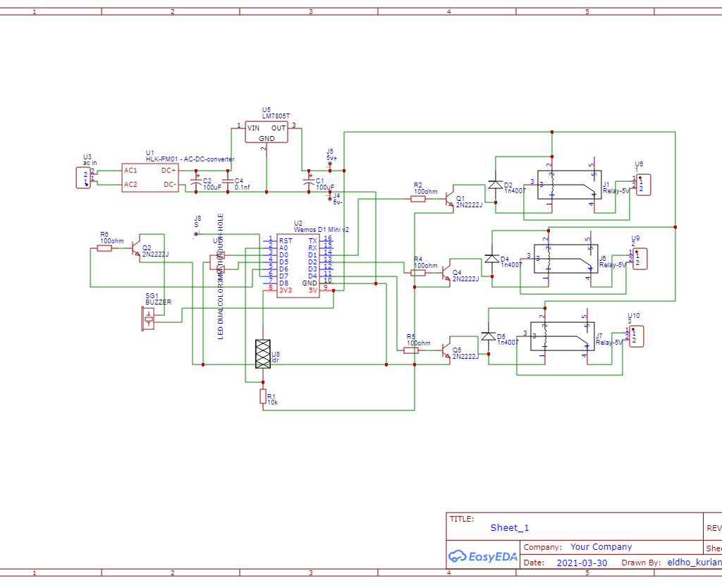
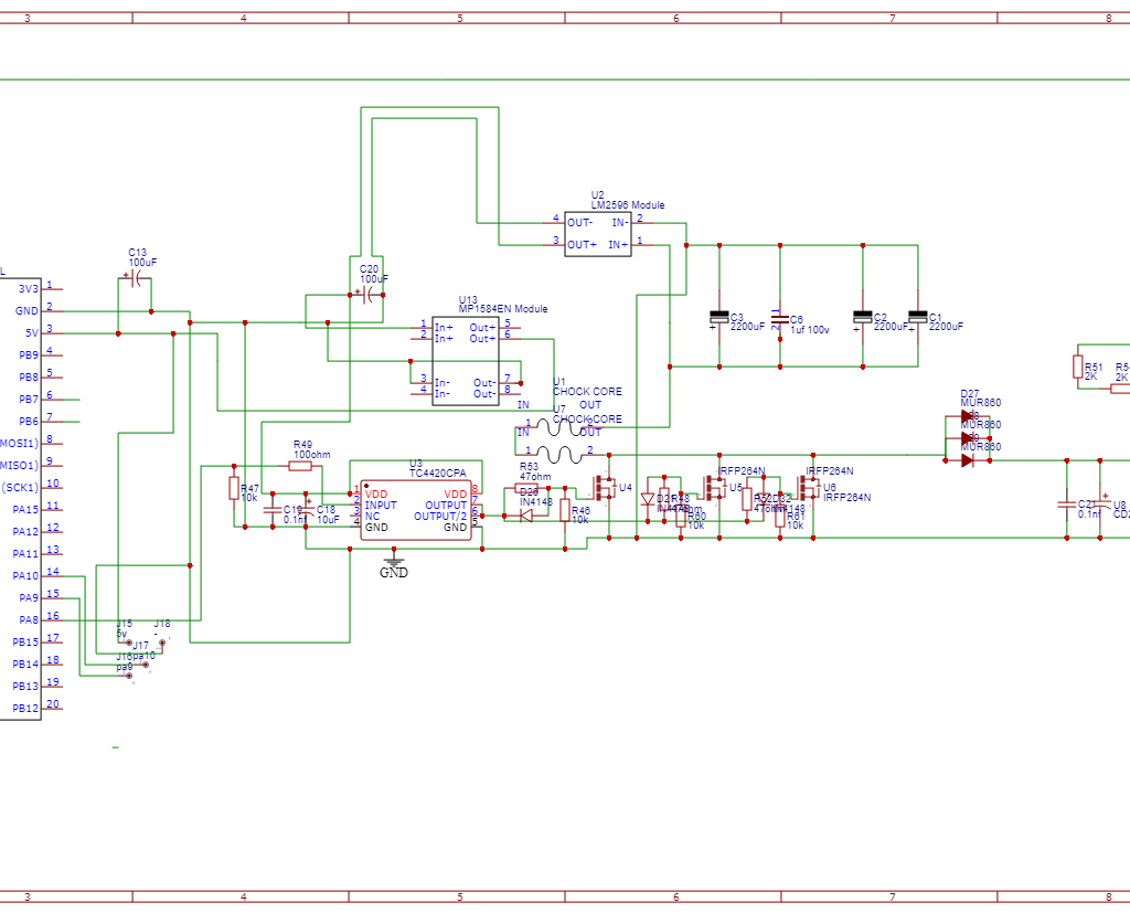
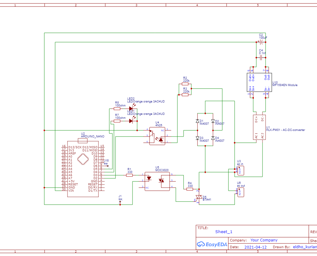
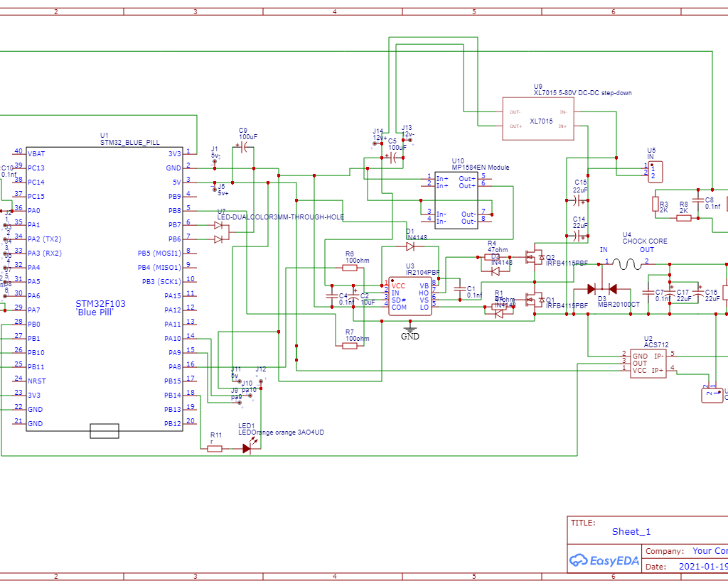
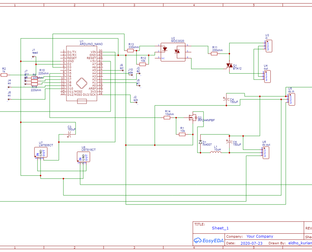
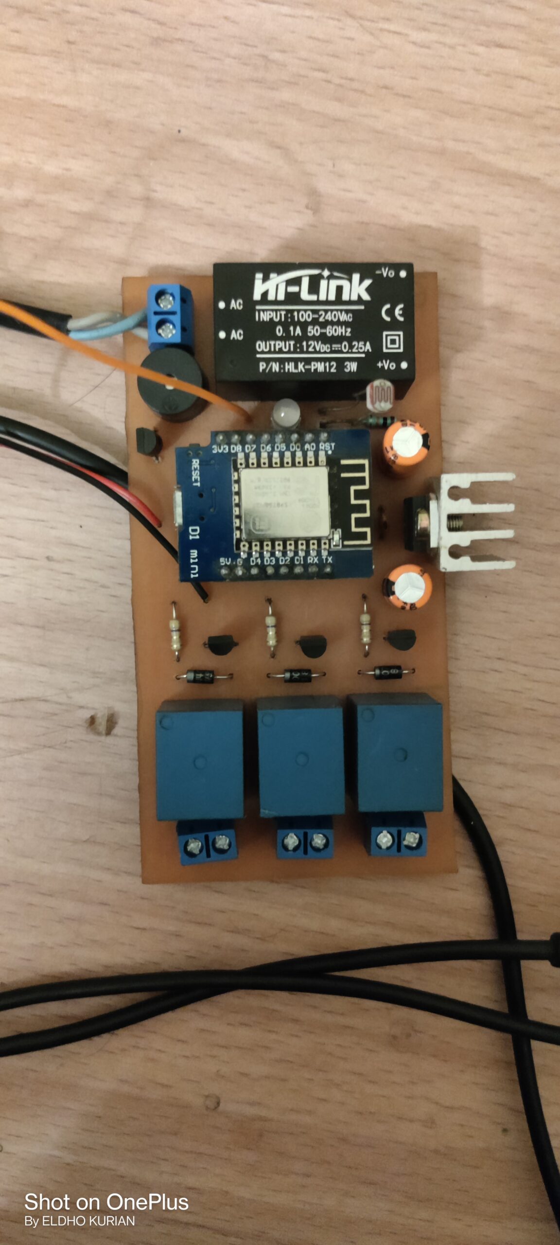
Schematic

Code and Gerber files

https://github.com/ELDHO-KURIAN/esp8266-VOICE-CONTROLLED-HOME-AUTOMATION-WITH-AMAZON-ALEXA

IMG_20210202_172550

DIY Boost Converter

What is a boost converter

A boost converter (step-up converter) is a DC-to-DC power converter that increases voltage from its input (supply) to its output while decreasing current (load). This type of switched-mode power supply (SMPS) has at least two semiconductors (a diode and a transistor) and at least one energy storage component, such as a capacitor, inductor, or both. In order to reduce voltage ripple, filters built of capacitors are typically attached to such a converter’s input (load-side filter) and output (occasionally in conjunction with inductors) (supply-side filter).

Working

A boost converter’s fundamental operation consists of two separate states 

In the off-state, the switch is open and the only path available for inductor current is through the flyback diode D, the capacitor C, and the load R. In the on-state, the switch S  is closed, increasing the inductor current. As a result, the energy accumulated during the on-state is transferred into the capacitor.
The input current is identical to the inductor current. In contrast to a buck converter, it is not discontinuous, and the criteria for the input filter are less stringent.

Diagram

Test

For detailed schematic, code, PCB files visit my GitHub page

https://github.com/ELDHO-KURIAN/DIY-PROGRAMMABLE-BOOST-CONVERTER

IMG_20210416_085327__01

DIY Phase Angle Controlled Soft Starter

What is a soft starter

The soft starter is a particular kind of motor starter that lowers the voltage while the motor is beginning by using the voltage reduction approach.

During motor startup, the soft starter gives a progressive increase in voltage. This will enable the motor to gradually pick up speed and accelerate. It stops any mechanical tearing or jerking brought on by an abrupt supply of full voltage.

How it works

The number of anti-parallel linked thyristors is contained in Soft Starter. Thyristors are present in pairs for each phase.
A thyristor is a semiconductor device that is typically isolated, but when a firing signal is applied to the gate, they begin to conduct and permit the passage of current and voltage.
Thyristors are fired at the appropriate time to accomplish soft beginning, only allowing the final half of each sinusoidal voltage pulse to pass through them.
Additionally, after the firing signal is sent, it is sent earlier and earlier so that a larger and larger portion of the voltage wave can travel through the thyristor.
Eventually, a firing signal is sent after each time a zero is crossed, allowing the thyristor to accept 100% of the voltage.
The opposite is done when stopping.

The firing signal is delivered later and later as the stop initiates, allowing less and less of the voltage to flow through until the end voltage is achieved. Initially, the full voltage is allowed to pass through the thyristors. The motor then stops when no more voltage is provided to it.
Start: The thyristor initially permits a little amount of voltage through it before ramping up in accordance with the starting ramp-up time.
Stop: The thyristor is fully conducting when the soft stop starts, and the voltage falls as the ramp time for the stop is set.

Starting results in lower voltage, which causes current and torque to fall as well.
The current will be reduced to roughly 50% of the maximum current at that speed and the torque will be reduced to around 25% of the maximum torque if the voltage is reduced to 50% of the full voltage.

Advantages

Improved Efficiency: Due to the low on-state voltage, softstarter systems with solid-state switches operate more efficiently.

Controlled startup: A major benefit of the soft starter is that the starting voltage can be readily changed to control the starting current, ensuring a smooth start of the motor without any jerks.

Acceleration under control: A soft starter is used to gradually manage motor acceleration.

Solid-state switches are used to achieve low cost and small size.

Circuit

Test and Results

The device was tested in a 1HP motor and following results were observed

Get the detailed circuit, PCB file, code on my GitHub page

https://github.com/ELDHO-KURIAN/DIY-AC-PHASE-ANGLE-CONTROLLED-SOFT-STARTER

IMG_20210125_130544

DIY Programmable Buck Converter

What Is a Buck Converter

A buck converter (step-down converter) is a DC-to-DC power converter that reduces voltage from its input (supply) to its output while increasing current (load). It belongs to a subcategory of switched-mode power supplies (SMPS) that typically includes at least two semiconductors (a diode and a transistor, though modern buck converters frequently replace the diode with a second transistor used for synchronous rectification) and at least one energy storage component, such as a capacitor, inductor, or the two separately or together. In order to reduce voltage ripple, filters built of capacitors are typically attached to such a converter’s input (load-side filter) and output (occasionally in conjunction with inductors) (supply-side filter). 

Advantage Over Normal Converters

In comparison to linear regulators, which are more straightforward circuits that lower voltages by dissipating power as heat but do not step up output current, switching converters (such as buck converters) offer a far greater level of power efficiency as DC-to-DC converters. 

Buck converters are useful for jobs like converting a computer’s primary supply voltage, which is often 12 V, down to lower voltages needed by USB, DRAM, and the CPU, which are typically 5, 3.3, or 1.8 V. Buck converters’ efficiency can be quite high, frequently exceeding 90%.

Read more about buck converter : https://en.wikipedia.org/wiki/Buck_converter

Features

  1. wide input ranging from 15v to 80v
  2. wide output ranging from 16v to 70v
  3. has current limiting which can be set from 0 to 10A
  4. high efficiency(90to95%)
  5. over current and short circuit protection
  6. RGB led which change color according to mode

Schematic

Calculations

https://www.youtube.com/watch?v=f2JEUacdmig&list=WL&index=2 this video is not made by me .

Find detailed schematic, PCB and code in my GitHub page

https://github.com/ELDHO-KURIAN/DIY-PROGRAMMABLE-BUCK-CONVERTER

IMG_20200725_164713

DIY SMD Reworking Station

WARNING !

This projects requires working on mains voltage, mishandling can possibly lead to injuries or even death

Advantages Of Hot Air Reworking

For speedy completion of modest tasks, hot-air rework stations are perfect. An old circuit board’s components are easy to remove with the use of a hot air . Even though this method isn’t precisely surgical, it will still save you a lot of time, in fixing existing soldered components, and pieces that would otherwise have been thrown out with the circuit board. Another advantage of using a hot-air rework station is that it also functions as a soldering station. This means that you can quickly solder a resistor, for example, and solder on a new resistor to save time.

What Is PID Control

A feedback-based control loop mechanism known as a proportional-integral-derivative controller (PID controller or three-term controller) is frequently employed in industrial control systems and a number of other applications that call for constantly modulated control. With respect to a desired setpoint (SP) and a measured process variable (PV), a PID controller constantly calculates an error value (displaystyle e(t)) and applies a correction based on proportional, integral, and derivative terms (denoted P, I, and D, respectively).

Practically speaking, PID automatically corrects a control function in a precise and timely manner. A common example is the cruise control on a car, which would slow down if engine power was applied continuously while it ascended a slope. The PID algorithm of the controller returns the observed speed to the

Features

  1. heats up within 5 seconds
  2. automatically reach to set temperature when you pick up the handle
  3. when you put back the handle in the holder machine goes to cooling mode and fan spins until the temperature goes below 50 degree Celsius
  4. if the fan speed is too low at very high temperature the heating element shuts down and gives warning on LCD
  5. machine works based on PID hence it can hold the heating element at the set temperature
  6. RGB led which change color according to mode

Libraries Required

you can download the librarys fron electronoobs
https://www.electronoobs.com/eng_arduino_liq_crystal.php
https://www.electronoobs.com/eng_arduino_max6675.php

Diagram

Find Detailed Diagram, Code, PCB file on my GitHub

https://github.com/ELDHO-KURIAN/smd-reworking-station

PWM-signal-with-its-two-basic-time-periods

Understanding PWM (stm32,Esp32,Arduino)

What is PWM

By dividing an electrical signal into discrete pieces, pulse-width modulation (PWM) or pulse-duration modulation (PDM) is a technique for lowering the average power produced by an electrical signal. By rapidly flipping the switch between the supply and the load on and off, the average amount of voltage (and current) provided to the load is managed. The total power provided to the load increases while the switch is on for a longer period of time compared to when it is off.

Calculations

Available duty cycle = (2^bit)-1

Maximum frequency = clock frequency/2^bit

example : bit=10,clock frequency=8Mhz

Available duty cycle = (2^10)-1 = 1023

Maximum frequency = 80000000/2^10 = 78.125khz

PWM in stm32

HardwareTimer timer(1);  //select timer 

void setup() {
pinMode(PA8, PWM);  //set PA8 as pwm pin
timer.setPrescaleFactor(1);   //select prescaler
timer.setOverflow(1024); //set duty cycle from calculation 
}

void loop() {
pwmWrite(PA8,pwm_value);  //write the pwm value to PA8
}

PWM in Esp32

const int ledPin = 16;  // 16 corresponds to GPIO16

// setting PWM properties
const int freq = 5000; //set the maximum frequency from calculating max frequency avalible for the resolution you selected from formula
const int ledChannel = 0;
const int resolution = 8; //set resolution 
 
void setup(){
  ledcSetup(ledChannel, freq, resolution);  // configure 
 
  ledcAttachPin(ledPin, ledChannel); // attach the channel to the GPIO to be controlled
}
 
void loop(){
  // increase the LED brightness
  for(int dutyCycle = 0; dutyCycle <= 255; dutyCycle++){   
    // changing the LED brightness with PWM
    ledcWrite(ledChannel, dutyCycle);
    delay(15);
  }

  // decrease the LED brightness
  for(int dutyCycle = 255; dutyCycle >= 0; dutyCycle--){
    // changing the LED brightness with PWM
    ledcWrite(ledChannel, dutyCycle);   
    delay(15);
  }
}

PWM on Arduino

//Initializing LED Pin
int led_pin = 6;
void setup() {
  
  pinMode(led_pin, OUTPUT); //Declaring LED pin as output
}
void loop() {
  //Fading the LED
  for(int i=0; i<255; i++){
    analogWrite(led_pin, i);
    delay(5);
  }
  for(int i=255; i>0; i--){
    analogWrite(led_pin, i);
    delay(5);
  }
}

How to configure fast PWM on Arduino

pinMode(3, OUTPUT);
pinMode(11, OUTPUT);
TCCR2A = _BV(COM2A0) | _BV(COM2B1) | _BV(WGM21) | _BV(WGM20);
TCCR2B = _BV(WGM22) | _BV(CS22);
OCR2A = 180;
OCR2B = 50;

Output A frequency: 16 MHz / 64 / (180+1) / 2 = 690.6Hz

Output A duty cycle: 50%

Output B frequency: 16 MHz / 64 / (180+1) = 1381.2Hz

Output B duty cycle: (50+1) / (180+1) = 28.2%

A good explanation of setting fast PWM on Arduino is provided in the Arduino website

https://docs.arduino.cc/tutorials/generic/secrets-of-arduino-pwm