
What is a boost converter
A boost converter (step-up converter) is a DC-to-DC power converter that increases voltage from its input (supply) to its output while decreasing current (load). This type of switched-mode power supply (SMPS) has at least two semiconductors (a diode and a transistor) and at least one energy storage component, such as a capacitor, inductor, or both. In order to reduce voltage ripple, filters built of capacitors are typically attached to such a converter’s input (load-side filter) and output (occasionally in conjunction with inductors) (supply-side filter).
Working
A boost converter’s fundamental operation consists of two separate states
In the off-state, the switch is open and the only path available for inductor current is through the flyback diode D, the capacitor C, and the load R. In the on-state, the switch S is closed, increasing the inductor current. As a result, the energy accumulated during the on-state is transferred into the capacitor.
The input current is identical to the inductor current. In contrast to a buck converter, it is not discontinuous, and the criteria for the input filter are less stringent.
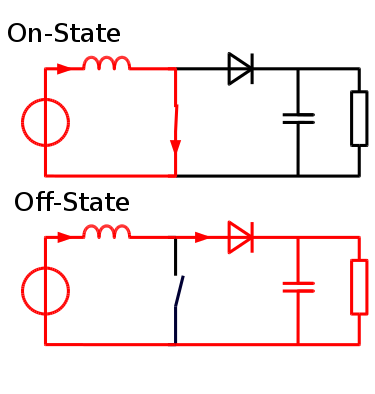
Diagram
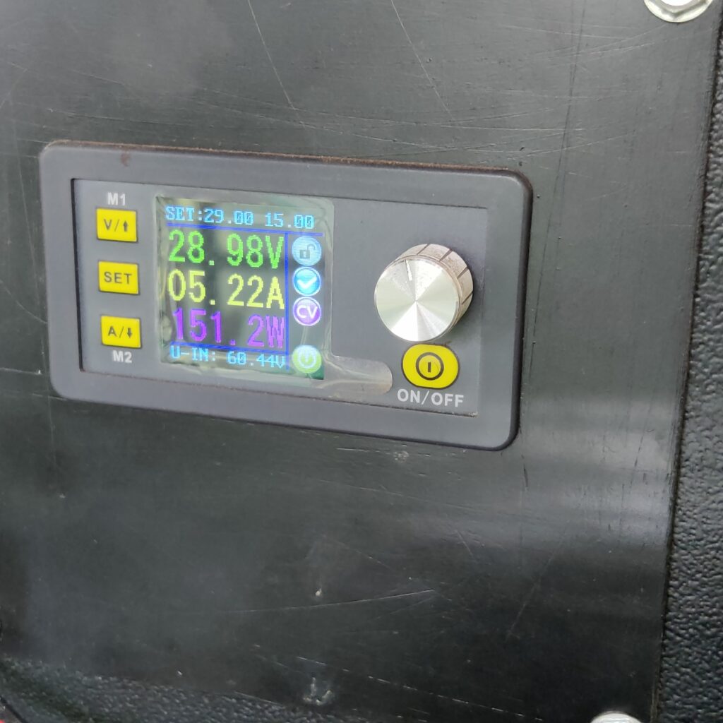
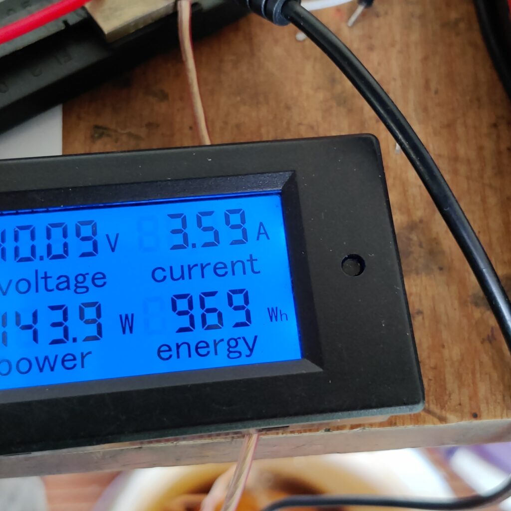
Test
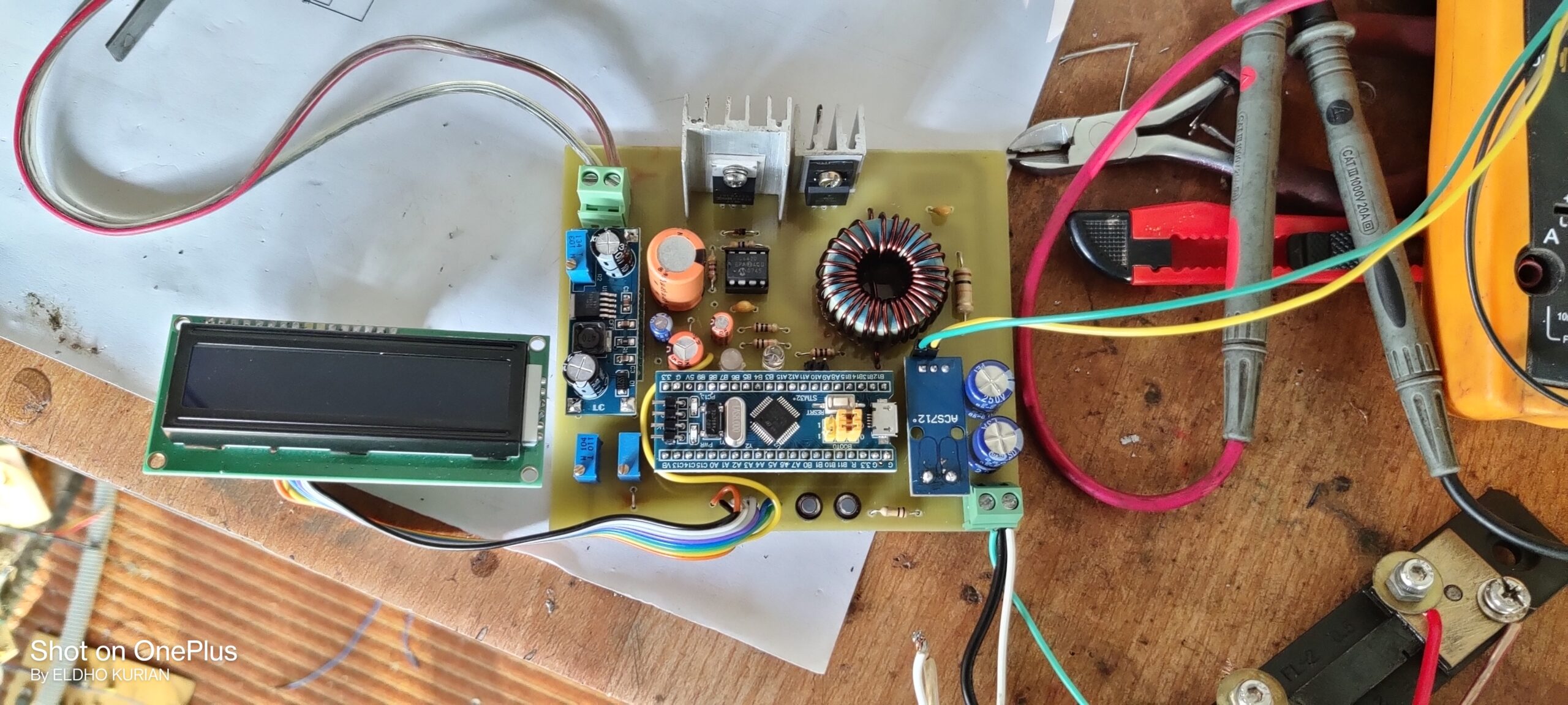
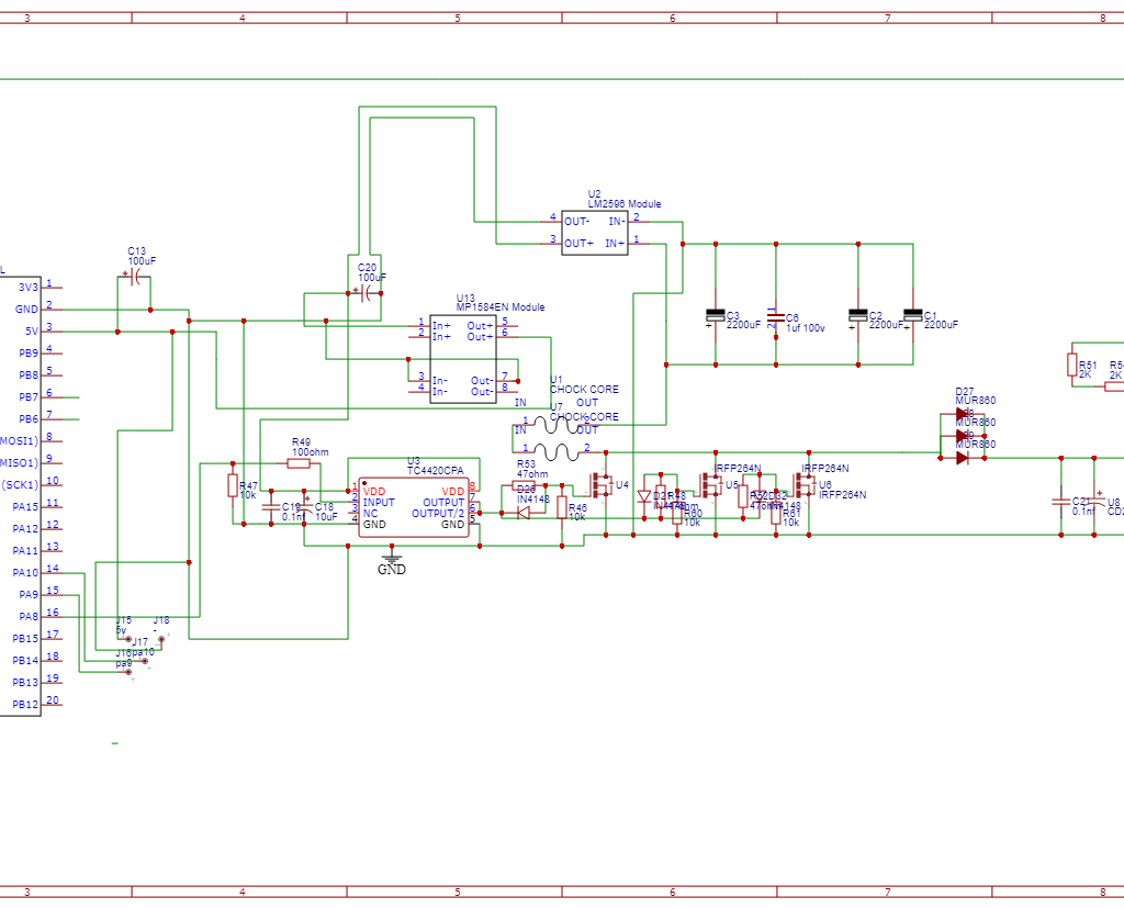
For detailed schematic, code, PCB files visit my GitHub page
https://github.com/ELDHO-KURIAN/DIY-PROGRAMMABLE-BOOST-CONVERTER