

What Is a Buck Converter
A buck converter (step-down converter) is a DC-to-DC power converter that reduces voltage from its input (supply) to its output while increasing current (load). It belongs to a subcategory of switched-mode power supplies (SMPS) that typically includes at least two semiconductors (a diode and a transistor, though modern buck converters frequently replace the diode with a second transistor used for synchronous rectification) and at least one energy storage component, such as a capacitor, inductor, or the two separately or together. In order to reduce voltage ripple, filters built of capacitors are typically attached to such a converter’s input (load-side filter) and output (occasionally in conjunction with inductors) (supply-side filter).
Advantage Over Normal Converters
In comparison to linear regulators, which are more straightforward circuits that lower voltages by dissipating power as heat but do not step up output current, switching converters (such as buck converters) offer a far greater level of power efficiency as DC-to-DC converters.
Buck converters are useful for jobs like converting a computer’s primary supply voltage, which is often 12 V, down to lower voltages needed by USB, DRAM, and the CPU, which are typically 5, 3.3, or 1.8 V. Buck converters’ efficiency can be quite high, frequently exceeding 90%.
Read more about buck converter : https://en.wikipedia.org/wiki/Buck_converter
Features
- wide input ranging from 15v to 80v
- wide output ranging from 16v to 70v
- has current limiting which can be set from 0 to 10A
- high efficiency(90to95%)
- over current and short circuit protection
- RGB led which change color according to mode
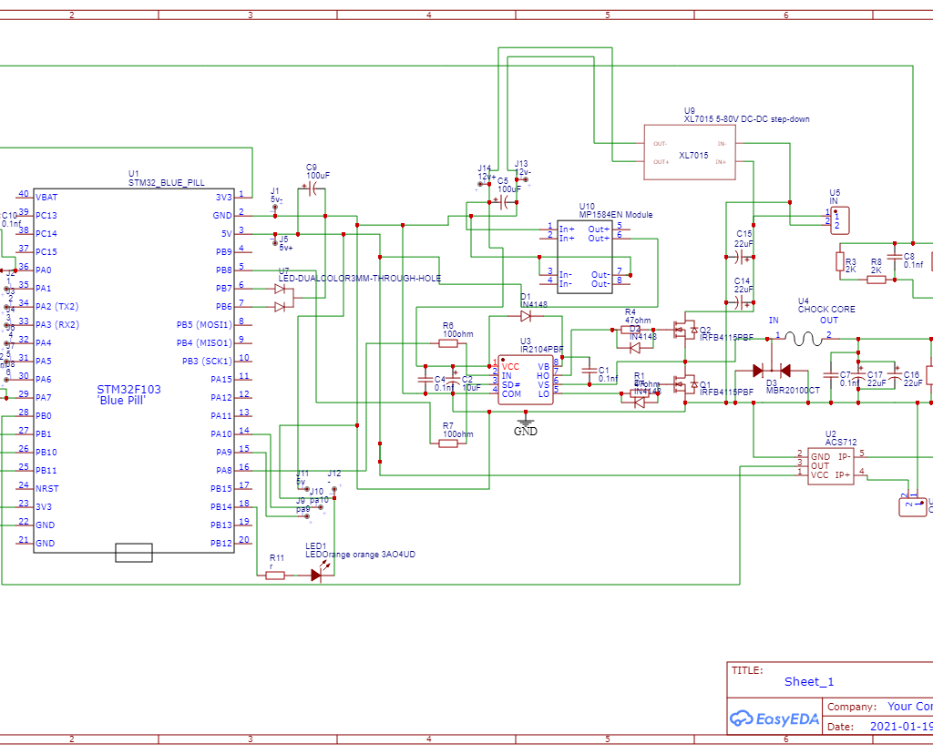
Schematic
Calculations
https://www.youtube.com/watch?v=f2JEUacdmig&list=WL&index=2 this video is not made by me .
Find detailed schematic, PCB and code in my GitHub page
https://github.com/ELDHO-KURIAN/DIY-PROGRAMMABLE-BUCK-CONVERTER